Emergent Pavillion
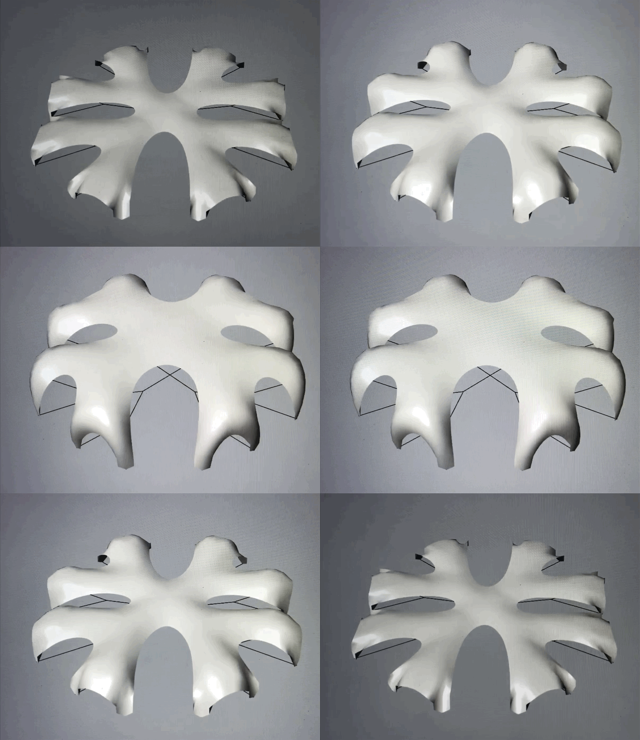
The workshop focused on performance-driven design methodology to explore how computational tools, such as structural simulation, can be incorporated into the design process to yield an intelligent and informed design outcome. The goal is to digitally generate a 3D mesh using grasshopper to simulate gravitational forces on a line pattern, with the goal of creating a physical self-supporting pavilion. We went through various test models, both digital and physical, to come up with a triangulated truss geometry which provides surface tension and strength in our final pavilion.
Cardiff, Wales
BSc Year 2 : Vertical Studio
Tutor: Kwanphil Cho, Zaha Hadid Architects
DIGITAL FABRICATION
As we only had two weeks to complete the project, we started with a final design, so we could start testing the materials as soon as we could. The patterns we created had to be optimised to avoid folds in and create a viable final mesh when input into grasshopper to simulate pressure, spring and gravitational forces as fluid 3D mesh.


To extract a final 3D mesh, we stopped the simulation when the form was how we wanted it and baked it.


Throughout the project, we designed our own pavilions using basic form finding in rhino to create patterns inspired by nature with varying aspects such as branch length, angles, and the number of branches and divisions.
For our first attempt, we varied the length, number and angle of the branches throughout the evolutions below; the 4th evolution is a combination of the best elements of it's 3 predecessors.
LENGTH OF BRANCHES
NUMBER OF BRANCHES
ANGLE OF BRANCHES
EVOLUTION 1


PATTERN
PLAN VIEW
SIDE VIEW
PERSPECTIVE


PATTERN
PLAN VIEW
SIDE VIEW
PERSPECTIVE


PATTERN
PLAN VIEW
SIDE VIEW
PERSPECTIVE


EVOLUTION 2


EVOLUTION 3


EVOLUTION 4


- larger designs with greater distance between anchor points


- larger, slender and more intricate mesh pavilion
- more diverse as the number of anchor points were increased


- variation of larger and smaller openings as the anchor points were adjusted
After our first attempt, we noticed the conventionality of the structure therfore wanted to create something more complex and unique. Taking inspiration from the previous iterations, we created a new set focussing on the same parameters of angle and number of branches.
1
x
x
2
3
x


x = 3


x = 4


FURTHER ITERNATIONS WITH SAME BRANCH #
x = 5


x = 6


After baking these iterations, we noticed the reoccurance of a spiral shape and therefore decided to look further into this.
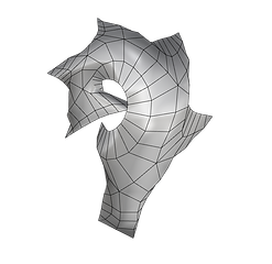
Using the voronoi spiral and its opposite, a delaunay edges spiral, to create 2D plans, we created our final structures based on biomimicry.


Finally we looked at a spiral based on delaunay edges...
... and, its inverse, a voronoi spiral.
Using the voronoi spiral to create 2D plans, we created our final structures based on biomimicry.
STRESS ANALYSIS
To test how our structure would cope under real world forces and where it might need support, we analysed the form using Millipede, a grasshopper extension.
We first created a mesh visualisation and 1st principle stress lines showing where the maximum stress occurs and how this stress is distributed throughout the form. First, we needed to select points on the mesh to use for the the stress line analysis


Using von Mises theory for brittle materials, the rainbow visualisation mesh shows the maximum estimated stress the form can undergo without exceeding the ultimate tensile strength of our material.
Stress lines are curves that at each point are tangent to one of the principle stress directions, there are two principle stress lines emanating from each single point on the mesh. We used the 1st principle stress line as it gives the maximum value of stress that is normal to the plane in which the shear stress is 0; the ground
PHYSICAL MODEL BUILDING PROCESS
We first had to translate the digital model to one we could physically build by breaking the 3D model into strips, made up of quadrilaterals, and then unrolling these into 2D components. To ensure that they were easy to connect to form the pavilion, we added folds to the outside of the components so we could staple them together.
We first had to translate the digital model to one we could physically build by breaking the 3D model into strips, made up of quadrilaterals, and then unrolling these into 2D components. To ensure that they were easy to connect to form the pavilion, we added folds to the outside of the components so we could staple them together.


To laser cut these components, we had to break them up to fit onto the A1 sheets, with numbered flaps that we could easily assemble with staples.
We then had to testing two materials to see which was stronger and more able to hold its own weight while being aesthetically pleasing. We chose the white card, and printed all the components onto 40 A1 sheets.
To assemble it we then stapled together the components to form quaters, then eighths, then quarters, then the whole.
 |  |  |  |  |  |  |
|---|---|---|---|---|---|---|
 |  |  |  |  |  |  |
 |
 |  |  |  |  |
|---|---|---|---|---|
 |  |  |  |  |
 |  |  |  |  |


